Ship hull design explained: the shape beneath the waterline
A detailed guide to hull shape, bulbous bows, resistance, stability and structure, with worked examples, five original diagrams and engineering videos.
By Alykhan Virani · 15 min read · Published
More in Shipbuilding →Running a giant series →Try the engineering lab →
Contents · 18 sections
A hull begins with a job
A ship’s hull is its watertight body, but its design reaches far beyond the outline visible from a harbour. The shape must support the vessel’s weight, provide useful internal space, pass through water efficiently and withstand loads throughout its working life. A handsome bow is only one part of that problem. Much of the important geometry stays underwater, and the most efficient shape depends on what the ship is expected to do.
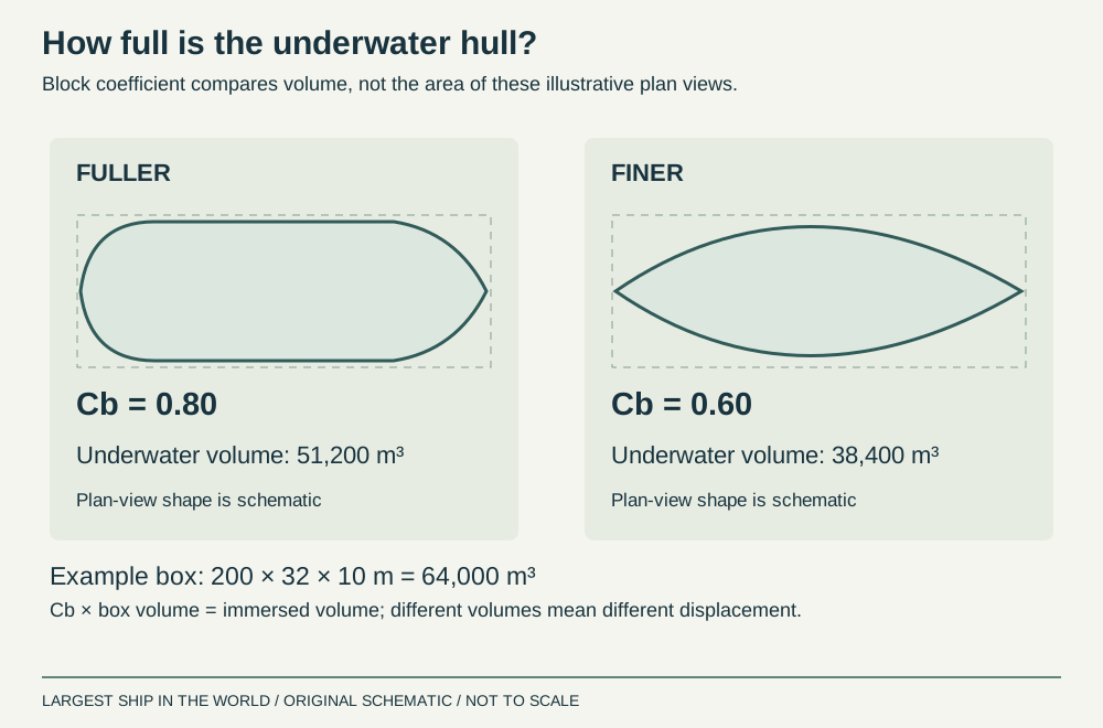
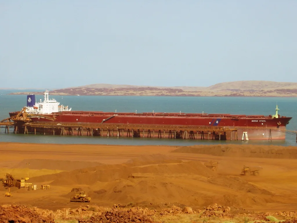
Consider two imaginary commissions: an ore carrier carrying dense cargo between deep-water terminals, and a passenger vessel keeping a demanding schedule with comfortable accommodation. Giving both the same hull would ignore their different priorities. Before drawing either, a designer needs a route, payload, range, operating speeds, loading conditions and port restrictions. These become the design brief. MARIN describes optimising hulls for a vessel’s expected operating profile, including relevant weather, rather than just one contractual speed. That approach turns “Which hull is best?” into a more useful question: “Best for which voyage, carrying what, and how often?”
Sources: [1] MARIN: optimisation for an operational profile ↗

Buoyancy: how steel stays afloat
A floating ship displaces a volume of water whose mass matches the ship’s total mass. The steel itself is denser than water, but the hull encloses enough volume to make the whole vessel buoyant. Displacement includes the structure, machinery, cargo, fuel, stores and everyone aboard. It changes as the ship is loaded or consumes supplies. Gross tonnage, by contrast, measures enclosed volume through a convention-based calculation; it is not the weight pushing down on the sea.
Take a simplified vessel with a total mass of 30,750 tonnes. In water with an assumed density of 1.025 tonnes per cubic metre, it must displace 30,000 cubic metres. This is an illustrative calculation, not a specification for a real ship. Put the same mass in fresh water at 1.000 tonne per cubic metre and it needs 30,750 cubic metres underwater. Its waterline changes accordingly. That is why a photograph of a lightly loaded ship cannot reveal the underwater shape it presents when fully loaded.
Sources: [2] Wärtsilä: displacement ↗
Reading the shape: length, beam, draught and lines
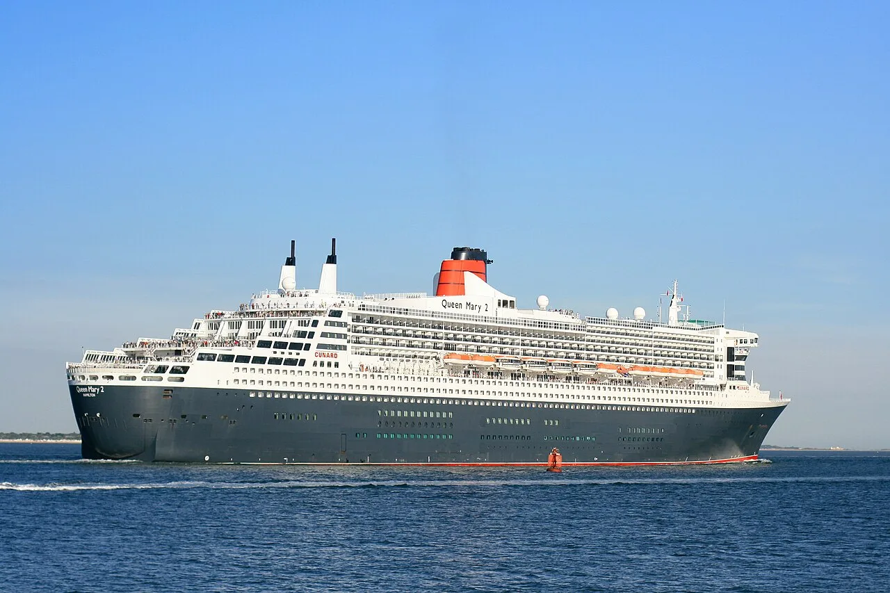
Length needs a definition. Overall length measures the vessel’s extreme ends; waterline length describes its intersection with the water at a particular condition; length between perpendiculars uses defined design reference points. Substituting one for another can quietly spoil a calculation. Beam is width. Draught is the vertical distance from the relevant bottom reference to the waterline. Depth is a structural dimension to a deck, while freeboard measures the height above the waterline to the applicable deck reference.
A lines plan makes a curved surface readable through coordinated views. The profile shows the hull from the side. The half-breadth plan shows horizontal waterlines viewed from above. The body plan shows transverse sections, like slices through a loaf. Together they describe how the hull narrows toward the ends and changes with height. A drawing of the above-water silhouette alone cannot do this. When looking at a lines plan, follow one waterline across the views and then one transverse section. Each is a different description of the same three-dimensional surface.
Sources: [3] Wärtsilä: lines and lines plans ↗
Fullness: the block coefficient explained
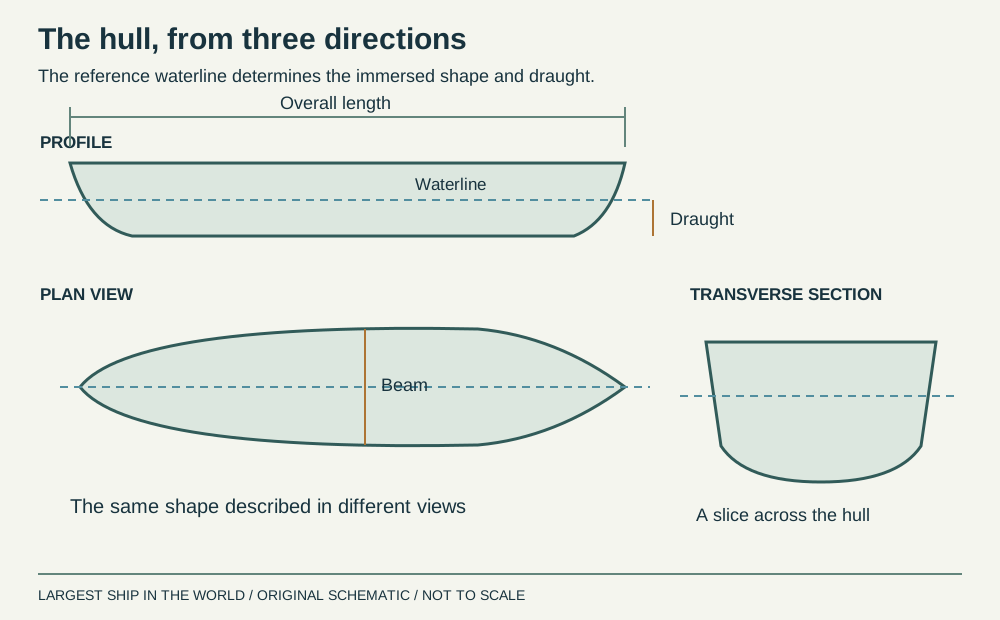
The block coefficient, Cb, compares underwater volume with a rectangular box of specified length, breadth and draught: Cb = volume ÷ (L × B × T). All dimensions must use compatible conventions. Wärtsilä’s definition uses length between perpendiculars. A fuller shape occupies more of that box; a finer shape occupies less. Cb describes volume distribution in a broad sense. It does not, on its own, establish speed, stability or fuel consumption.
For an illustrative 200 m × 32 m × 10 m box, the volume is 64,000 cubic metres. At Cb = 0.80, the immersed hull occupies 51,200 cubic metres. At Cb = 0.60, it occupies 38,400. These two hypothetical shapes therefore do not carry the same displacement at that draught. This matters when comparing attractive drawings: a slimmer hull may simply contain less useful volume. A fair design comparison must restore the required payload, perhaps by changing length or draught, and then assess the resulting vessel again.
Sources: [4] Wärtsilä: coefficients of form ↗

Resistance: where the energy goes
Moving water out of the way costs energy. Friction acts along the wetted hull as water flows past it. The pressure distribution around the shape also resists motion, and the ship expends energy creating waves. Above the water, wind acts on the superstructure and deck cargo. Appendages such as bilge keels and rudders add their own contributions. The proportions vary with vessel type, speed and condition, so a single pie chart cannot represent every ship.
A simple power calculation makes the scale tangible. If a hypothetical hull experiences 1,000 kilonewtons of resistance while travelling at 10 metres per second, the effective towing power is 10 megawatts: force multiplied by speed. The engine or motor must supply more than that because propulsion and transmission are not perfectly efficient. Reducing resistance is therefore useful even before changing machinery. But removing one source of drag can worsen another. A smaller wetted area may require a fuller shape, for example, changing pressure and wave effects. Hull design balances the total.
Sources: [5] Wärtsilä: ship resistance ↗
Speed and length: why Froude number matters
Froude number compares speed with a length-dependent gravity scale: Fn = V ÷ √(gL). Use speed in metres per second, length in metres and gravitational acceleration of approximately 9.81 metres per second squared. The result has no units. It helps designers compare wave-related behaviour between geometrically similar hulls of different sizes. It is not a fuel-efficiency score or a universal speed limit.
At 20 knots, approximately 10.29 metres per second, an illustrative 200-metre waterline gives Fn ≈ 0.232. At that same speed, a 300-metre waterline gives Fn ≈ 0.190. The calculation helps explain why speed must be considered relative to length. It does not prove that the longer vessel needs less total power: its displacement, wetted surface and shape may all differ. Similarly, a dramatic bow wave in a photograph is not enough to calculate resistance. The operating condition and the complete wave system matter, including parts of the flow that a surface image cannot show.
Sources: [6] Wärtsilä: Froude number ↗
The bulbous bow: useful interference, carefully tuned
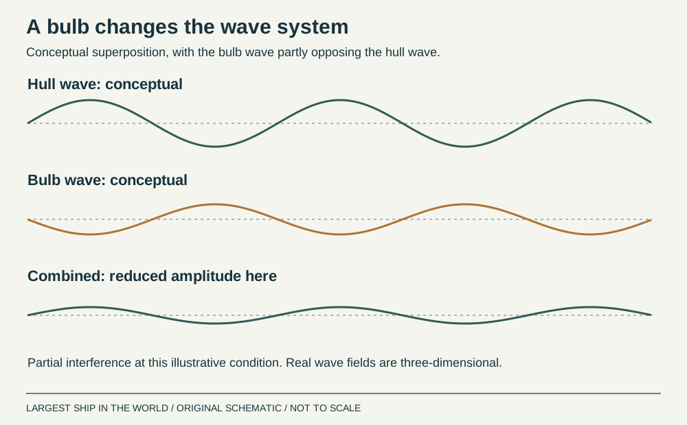
A bulbous bow changes the pressure and wave pattern ahead of the main hull. At suitable operating conditions, the bulb’s wave system can interact favourably with the hull’s wave system and reduce wave-making resistance. “Cancelling the bow wave” is an accessible shorthand, but it should not suggest that all waves vanish or that the bulb produces free energy. Its extra surface and altered flow also have costs.
Bulb size, depth and longitudinal position must suit the intended draughts and speeds. Change the loading condition and its immersion changes; change speed and the wave pattern changes. Research on bulb optimisation therefore considers multiple operating points rather than assuming the best result at one speed will remain best everywhere. A bulb developed for a fast service may deserve re-examination if the vessel spends much of its life steaming more slowly. For readers, the useful question is not whether a ship has a bulb, but whether that bulb matches the service being performed.
Sources: [7] Research: bulbous-bow optimisation under multiple operating conditions ↗
Inverted bows and the problem of entering waves
Some ships carry their bow volume differently, with an inverted profile that slopes back toward the upper deck. Ulstein’s X-BOW is a specific commercial design family within this broader discussion. The company describes distributing forebody volume to soften wave entry and reduce pitching and impact loads. Its design explanation and CFD comparison are included in the videos below. These are the designer’s presentations, so their performance claims should be read in that context.
The engineering question extends beyond appearance. How quickly does additional buoyancy develop as the bow enters a wave? How much does the vessel accelerate vertically? What happens to spray, deck wetness and forward working space? A change that benefits a particular offshore vessel does not automatically improve a tanker or container ship. Comparing bow types requires equivalent loading, speed and wave conditions, plus a clear measure of success. A simulation showing gentler motion is informative, but it does not by itself establish annual fuel savings on a different route.
Sources: [8] Ulstein: X-BOW hull design ↗
The stern must feed the propeller
Water reaching the propeller has already passed along the hull. Its velocity is neither uniform nor necessarily equal to the vessel’s speed through the water. Naval architects describe the difference using the wake fraction. The stern’s shape, and the propeller’s position and size, influence that inflow. This connects hull design directly to the propulsion system: evaluating the two separately can miss an important interaction.
Imagine a propeller blade rotating through alternating faster and slower water. Its loading changes during each revolution. The designer wants useful thrust while controlling the consequences of that uneven inflow, including vibration and cavitation risk. A stern modification that slightly changes bare-hull resistance might still improve the complete propulsion arrangement. Conversely, a smooth-looking stern may provide poor flow where the propeller actually operates. This is why model programmes include self-propulsion work as well as towing tests. The important result is the power needed to move the complete vessel, with its actual propulsion arrangement, at the required condition.
Sources: [9] Wärtsilä: wake fraction coefficient ↗ [19] MARIN: resistance and propulsion research ↗
Stability: floating is only the first requirement
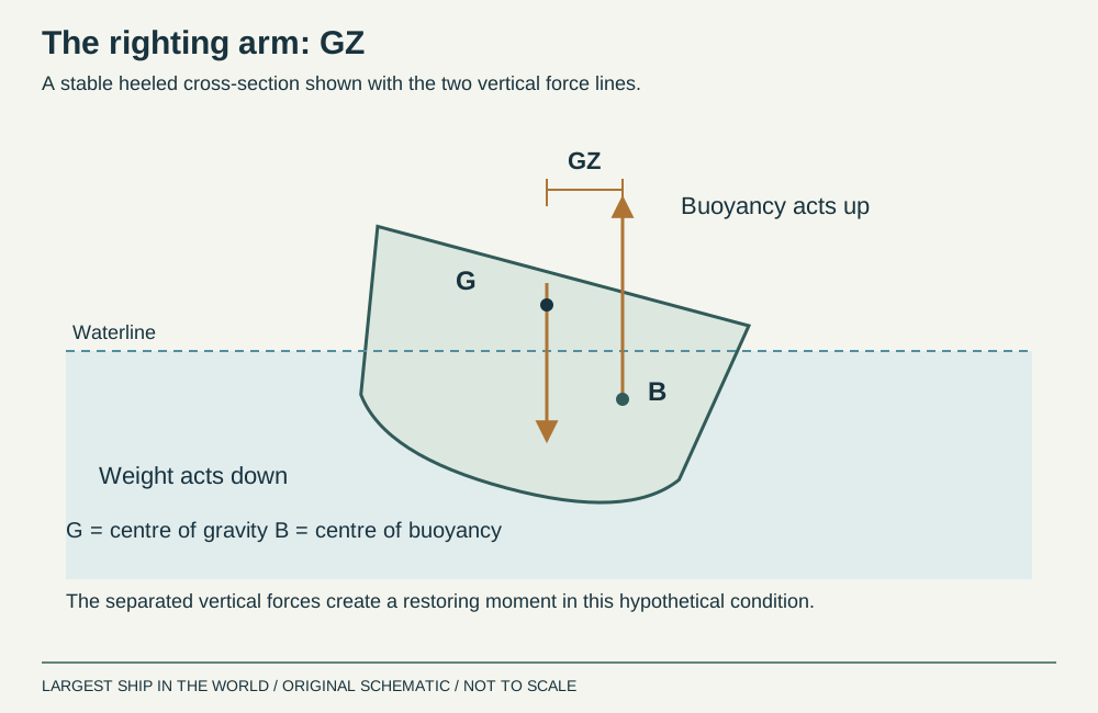
Buoyancy answers whether the ship can support its mass. Stability asks how it responds when inclined. As the hull heels, its immersed shape changes and the centre of buoyancy moves. The relationship between the upward buoyancy force and downward weight can create a moment that tends to return the vessel toward upright. Hull shape and the location of weights both matter.
This explains why an unchanged ship can behave differently after loading. Dense cargo high in the vessel has a different effect from the same mass low down. A ship’s tall appearance alone does not establish whether its stability is adequate, because photographs do not reveal the distribution of machinery, tanks and cargo. Nor does a wide beam settle the question. Designers assess loading conditions, and operators must remain within the approved limits. The conceptual diagram below shows the force relationship; it is not a stability assessment for any particular vessel, and its geometry is deliberately simplified to keep the principle readable.
Sources: [10] Wärtsilä: stability ↗
GM and the limits of a single number
For small angles of heel, metacentric height, GM, describes the separation between the centre of gravity, G, and the initial metacentre, M. A positive GM indicates an initial restoring tendency in the conventional upright condition. But “more GM” is not an unlimited improvement. A very stiff response can produce high accelerations, while a tender vessel develops smaller righting arms at small angles. Comfort, cargo loads and safety must be considered together.
The righting arm, GZ, is the horizontal separation between the lines of action of weight and buoyancy. At small angles, GZ is approximately GM × sin(heel angle). For an illustrative GM of 1 metre and a heel of 5 degrees, that gives about 0.087 metre. This is a teaching example only. At larger angles the full righting-arm curve and the geometry of openings become important, so extending that simple formula indefinitely would be misleading. One reassuring GM value cannot replace the wider stability evaluation.
Sources: [11] Wärtsilä: metacentric height ↗
Tanks, free surfaces and subdivision
A partly filled tank introduces another complication. As the vessel heels, the liquid redistributes, changing its centre of gravity and reducing the available restoring effect. This is called the free-surface effect. A broad, slack tank can therefore matter even when the liquid it contains seems relatively low in the hull. Tank arrangement and loading practice belong in the same design discussion as exterior shape.
Watertight subdivision addresses a different problem: limiting the spread of flooding after damage. Bulkheads divide the interior into compartments, but their effectiveness depends on the boundaries and the openings through them. Floodwater changes buoyancy, weight distribution and stability together. The design must consider damaged conditions as well as intact operation. IMO’s overview connects construction, subdivision and stability under SOLAS. That framework explains why “unsinkable” is an unhelpful label. A hull is evaluated against defined conditions and assumptions, and the protection depends on maintaining the integrity of the complete arrangement throughout service.
Sources: [12] Wärtsilä: free-surface effect ↗ [15] Wärtsilä: bulkheads ↗ [16] IMO: ship design, subdivision and stability ↗
Seakeeping: the ocean is not a towing tank
A hull that performs well in calm water still has to work in waves. The bow can rise out of the water and re-enter with a heavy impact, known as bottom slamming. Rapid immersion of a strongly flared bow can also produce impact loads. These events depend on the shape, loading condition and relative motion between ship and sea. A design must account for the loads and accelerations they create.
Think of the difference between a smooth-water speed demonstration and a winter voyage. The useful outcome on the voyage may be the ability to maintain an acceptable speed without excessive motion or impact. For a passenger ship, acceleration and comfort matter; for a working vessel, motion can interrupt the task it exists to perform. These are reasons to look beyond a single resistance figure. Model tests and calculations need representative wave conditions and headings. No bow profile can make the surrounding ocean irrelevant, and a good design still operates within a practical weather envelope.
Sources: [13] Wärtsilä: bow slamming ↗
Structure: the hull also works as a beam
The hull is a large structural system as well as a hydrodynamic surface. Shell plating, decks, inner bottom, longitudinal members and bulkheads contribute to the hull girder. Loads must pass through this connected structure. Simply making the outer skin thick would overlook the role of supporting members and the way forces travel between them.
Consider a long tray supported unevenly from below while carrying unevenly distributed weights. The analogy is imperfect, but it explains why the distribution of cargo and buoyancy matters, not just their equal totals. Designers examine global bending alongside local loading on individual panels and supports. Openings and changes in geometry must be incorporated into that load path. The useful distinction is between shape and scantlings: the former describes the geometry presented to the water, while the latter specifies structural sizes and thicknesses. Both have to be developed together. A promising underwater form is only a viable ship when the structure can carry its loads and be built and maintained.
Double hulls: separating the sea from the cargo
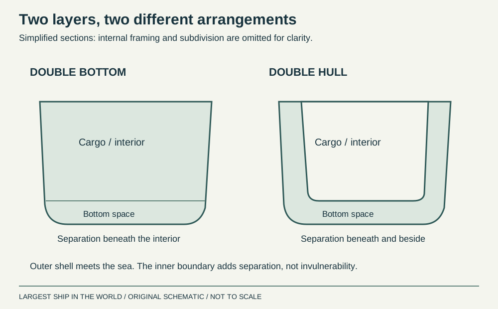
A double hull places an inner boundary inside the outer shell, creating intervening spaces along the bottom and sides in the relevant arrangement. A double bottom provides separation beneath the interior without necessarily extending that protection up the sides. Neither term means two separate floating hulls like a catamaran. The structural cutaway below shows the distinction conceptually rather than prescribing tank dimensions.
For oil tankers, this separation became a major part of pollution-prevention design. IMO describes the adoption of double-hull requirements and the subsequent phase-out programme for single-hull tankers. The practical principle is to create distance between an external breach and the cargo boundary. Protection is nevertheless finite: severe damage can penetrate both boundaries. Additional spaces also require access, inspection and maintenance. A double hull is consequently one element of the ship’s protective arrangement, not a promise that a collision cannot release cargo. Its value depends on the geometry, condition and nature of the damage being considered.
Sources: [17] IMO: oil-tanker double-hull construction ↗
From computer model to physical evidence
Computational fluid dynamics, or CFD, lets designers study flow around candidate shapes before committing to steel. It is especially useful for exploring variations systematically. The geometry, operating conditions and numerical assumptions must still be appropriate to the question being asked. A colourful pressure plot is a result to interpret, not a certificate of good design. MARIN combines computational development with experimental methods and full-scale evaluation.
Physical model tests provide another view. A towing test measures resistance; a self-propulsion test examines the hull and propeller working together; an open-water propeller test characterises the propeller in a more uniform inflow. Model-scale results require conversion to full scale rather than a simple multiplication of the measured force. The test programme should also document draught, trim, speed and appendages. Comparing two models without matching those conditions can attribute a difference to hull shape when another variable caused it. Strong evidence states what was tested, how the result was obtained and which operating conditions it represents.
Sources: [19] MARIN: resistance and propulsion research ↗ [18] Wärtsilä: model tests ↗
The working hull: trim and air
The delivered shape is only the starting point for operational performance. Trim describes the vessel’s fore-and-aft floating attitude. Changing it alters how the hull meets the water and how the propulsion arrangement operates. Wärtsilä describes using measured operating data to identify a suitable trim for particular conditions. There is no universal instruction to put every ship down by the bow or stern. Any adjustment must remain consistent with the vessel’s loading and operating limits.
Air lubrication tackles a different part of the problem by introducing air beneath the hull to reduce friction. Its net benefit must account for the energy required by the system, rather than quoting a local friction reduction as if it were whole-ship fuel savings. These examples show why a hull should be evaluated as an operating system. Shape, surface condition, loading and equipment interact. A new technology can be valuable, but the meaningful comparison is the total energy required for the same transport task under comparable conditions.
Sources: [20] Wärtsilä: operational performance and trim ↗ [21] Wärtsilä: air lubrication ↗
How to judge a hull-design claim
Start with the baseline. “Uses less power” needs a comparison vessel or configuration, and both need the same task. Ask whether the figure concerns towing power, shaft power or fuel consumption. Check the speed, displacement, draught, trim and weather. Then ask whether the result comes from a calculation, a model test, a sea trial or service measurements. Each can be useful, but they answer different questions and carry different uncertainties.
Finally, look for the trade-off. Has an improvement consumed cargo space, increased construction complexity or narrowed the conditions in which the ship performs well? Would the benefit survive a different operating schedule? The diagrams, calculations and photographs in this guide are tools for asking those questions, not shortcuts to choosing a vessel. A successful hull combines useful capacity, manageable resistance, suitable motions, adequate stability and structural strength. Its achievement is making those requirements work together over real voyages. That is what turns an interesting shape into a capable ship.
Watch the engineering in action
Sources & further reading
An editorial explainer based on the technical, research and industry references below.
- MARIN: optimisation for an operational profile ↗
- Wärtsilä: displacement ↗
- Wärtsilä: lines and lines plans ↗
- Wärtsilä: coefficients of form ↗
- Wärtsilä: ship resistance ↗
- Wärtsilä: Froude number ↗
- Research: bulbous-bow optimisation under multiple operating conditions ↗
- Ulstein: X-BOW hull design ↗
- Wärtsilä: wake fraction coefficient ↗
- Wärtsilä: stability ↗
- Wärtsilä: metacentric height ↗
- Wärtsilä: free-surface effect ↗
- Wärtsilä: bow slamming ↗
- Wärtsilä: girders and hull strength ↗
- Wärtsilä: bulkheads ↗
- IMO: ship design, subdivision and stability ↗
- IMO: oil-tanker double-hull construction ↗
- Wärtsilä: model tests ↗
- MARIN: resistance and propulsion research ↗
- Wärtsilä: operational performance and trim ↗
- Wärtsilä: air lubrication ↗