How ships reduce rolling: fins, tanks and gyroscopic stabilizers explained
How ships tame side-to-side motion at sea and at anchor, with detailed explanations of fins, anti-roll tanks, gyroscopes, control systems and their limits.
By Alykhan Virani · 15 min read · Published
More in Shipbuilding →Running a giant series →Try the engineering lab →
Contents · 19 sections
The short answer: reduce the motion, do not lock the ship upright
Ships reduce rolling through a combination of hull design, passive damping and controlled forces. Bilge keels resist side-to-side motion. Stabilizer fins push against the water. Anti-roll tanks use carefully timed liquid movement. Gyroscopic systems use a spinning flywheel and controlled precession. The appropriate combination depends on the vessel, its speed and the work it needs to perform. There is no single device fitted to every ship, and none makes the ocean stop moving.
On a large passenger vessel, much of this engineering is hidden below the waterline or inside the hull. A smooth-looking deck can therefore conceal equipment working continuously. But stabilization has a limited operating envelope: a system that is effective on a passage may perform differently at anchor, and a strong sea can exceed its available authority. Understanding that distinction makes the subject more interesting than the familiar claim that ships simply have underwater wings. The wings are real, but the complete explanation includes timing, power, loading and the ship’s own natural response.
Sources: [1] Wärtsilä: roll stabilisation ↗

Roll, pitch and heave are different motions
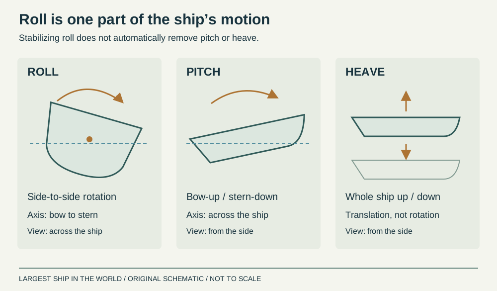
Roll is rotation about the ship’s fore-and-aft axis, making one side rise while the other falls. Pitch is rotation about a transverse axis, lifting the bow as the stern drops and then reversing. Heave is the whole vessel moving vertically. A ship also surges fore and aft, sways sideways and yaws about a vertical axis. These six motions can occur together.
A roll stabilizer principally targets the first of those movements. It does not automatically eliminate pitching, heaving or the impacts associated with entering waves. This is why passengers can still feel substantial motion even when roll control is working properly. Picture a tray held level while someone moves it up and down: keeping its sides even does not hold the tray still. Likewise, a video showing a flatter horizon demonstrates something about angular motion, but does not reveal every acceleration experienced by people or equipment aboard.
Sources: [2] Wärtsilä: ship motions ↗
Stability and stabilization solve different problems
A ship’s restoring tendency comes from the relationship between its weight and buoyancy as it heels. At small angles, metacentric height, GM, is an important measure of that initial tendency. A larger positive GM generally produces a stronger small-angle restoring moment, but it can also give a stiff, rapid response. A smaller GM can produce a slower, more tender response. Neither comfort nor safety can be judged from the speed of the visible roll alone.
Stabilization changes the motion produced by waves; it does not replace the ship’s required stability. This distinction is especially important when discussing ballast. Adding or moving weight changes loading, displacement and the centre of gravity, so it is not a universal remedy for an uncomfortable ride. The vessel’s approved loading arrangements remain fundamental. Think of restoring stability as the spring in an oscillating system and damping as a means of removing energy from the oscillation. A ship needs both suitable underlying characteristics and appropriate control of its response.
Sources: [3] Wärtsilä: metacentric height ↗
Why a gentle swell can produce a large roll
A vessel has a natural roll response shaped by its mass distribution, restoring properties and interaction with the surrounding water. If displaced and released in calm conditions, it can oscillate while its motion gradually decays. That decay reveals damping. Designers use roll-decay tests, among other methods, to investigate these characteristics. The period and damping change with the vessel and its condition.
Repeated wave forcing can build a large response when its timing suits the ship’s roll. The swing analogy is useful: modest pushes delivered at the right intervals can sustain a substantial oscillation. This is not a prediction that every regular swell causes a dangerous roll. Wave direction, encounter period, loading and damping all matter. It does explain why wave height alone is an incomplete description of how a voyage feels. Two seas of similar height can produce very different motion, and changing the ship’s speed or heading changes the pattern of waves it encounters.
Sources: [4] ITTC: estimation of roll damping, 2021 procedure ↗ [16] IMO: guidance on adverse weather and sea conditions, MSC.1/Circ.1228 ↗
Bilge keels: simple plates that dissipate energy
Bilge keels are long plates attached near the turn of the bilge, where the hull’s bottom curves into its sides. They are fixed to the structure rather than commanded to tilt like active fins. As the vessel rolls, they resist movement through the water and generate flow separation and vortices. Energy is transferred out of the roll motion into the surrounding flow.
Their appeal is simplicity. They have no motor or controller that must predict the next wave, and their damping action does not depend on forward speed in the same way as a conventional lifting fin. Their effect still depends on the flow and motion, so “passive” does not mean constant performance. Size, shape and attachment must be designed with structural loads and resistance in mind. A bilge keel is also different from a sailing yacht’s deep ballast keel: the commercial ship’s plate is primarily a roll-damping appendage, not a large weight suspended underneath the vessel.
Sources: [5] Wärtsilä: bilge keels ↗ [1] Wärtsilä: roll stabilisation ↗
Active fins: underwater foils with a changing angle
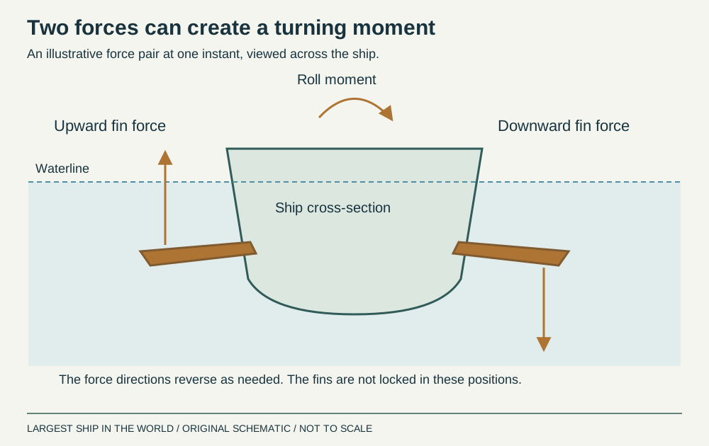
Active stabilizer fins project from the hull below the waterline. Water flowing around a fin develops a force whose magnitude and direction depend on its geometry, angle and relative water speed. By adjusting fins on the two sides, the system can generate a moment about the ship’s longitudinal axis. A simplified pair might push upward on one side and downward on the other to oppose a rolling tendency. The commanded forces change through the cycle.
Some fins retract into hull openings when not required; others remain outside the hull. Kongsberg describes its retractable Neptune range as suitable for cruise ships and larger ferries. Retraction can reduce the exposed appendage footprint, but it adds a mechanism and space requirement inside the ship. The installation is consequently more than the fin visible in a dry-dock photograph. It includes the hull unit, supporting structure, actuation, power supply and control equipment that make the foil move as intended.
Sources: [6] Kongsberg Maritime: fin stabilisers ↗
Why forward speed makes such a difference
A simplified lifting-force estimate is F = ½ρV²SCL, where ρ is fluid density, V is relative flow speed, S is reference area and CL is the lift coefficient. NASA presents this general fluid-dynamic relationship for aerodynamic lift; using water density applies the same principle to a submerged foil. Real fin performance additionally depends on installation, unsteady flow and operating limits.
For an illustrative 4-square-metre fin in seawater at 1,025 kilograms per cubic metre, with CL = 0.5 and flow speed of 5 metres per second, the estimate is 25,625 newtons, or about 25.6 kilonewtons. At 2.5 metres per second, keeping everything else fixed, the result is only about 6.4 kilonewtons. Halving speed quarters this idealised force. These are invented teaching inputs, not equipment specifications. If each of two fins produces 25.6 kilonewtons in opposite vertical directions at a 10-metre lever arm, their moments add to approximately 512 kilonewton-metres.
Sources: [7] NASA Glenn: the lift equation ↗
The controller matters as much as the fin
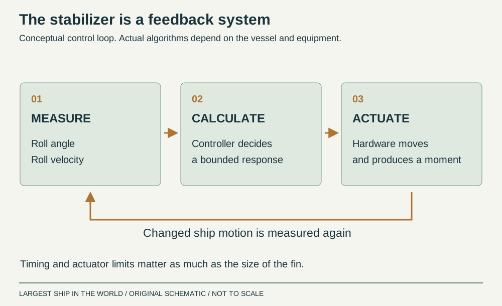
A fin should not simply point one way whenever the ship leans left and the other way whenever it leans right. The controller must account for the motion’s timing. Roll angle describes position; roll velocity describes how quickly that position is changing. Quantum explains that its controls interpret both measurements and use vessel-specific algorithms to direct the stabilizers.
That is a feedback loop: measure motion, calculate an appropriate response, move the hardware and measure the resulting motion again. Actuators have limits on force, speed and travel. Delay also matters, because a useful command can become poorly timed if delivered too late. The diagram below deliberately shows the loop rather than a purported universal algorithm. Actual control laws vary by supplier and installation. The aim is to reduce the measured response within the system’s available authority, while adapting to conditions. A larger fin cannot compensate indefinitely for unsuitable timing, just as a sophisticated controller cannot create unlimited force from a small actuator.
Sources: [8] Quantum: stabilizer control systems ↗
At anchor: the fins have to create their own flow
When the ship stops, conventional underway fins lose the steady forward flow that gives them much of their lifting ability. Stabilization at rest addresses that problem by moving specially designed fins through the water. Their motion produces hydrodynamic forces, with strokes timed to reduce roll. The result is not simply an ordinary fin held at a fixed angle while the vessel sits still.
Kongsberg describes modified fin geometry and active control for its stabilization-at-rest systems. Quantum’s accompanying video illustrates its own zero-speed approach. “Zero speed” identifies a capability, not a promise of zero motion. Fin area, stroke, actuation power, clearances and sea conditions all constrain the outcome. Motion of the ship itself also contributes to the relative flow. This helps explain why a vessel with excellent underway stabilization may need different equipment or operating modes for a comfortable anchorage. The design problem changes when forward motion is no longer supplying a steady stream of water.
Anti-roll tanks: using liquid motion at the right phase
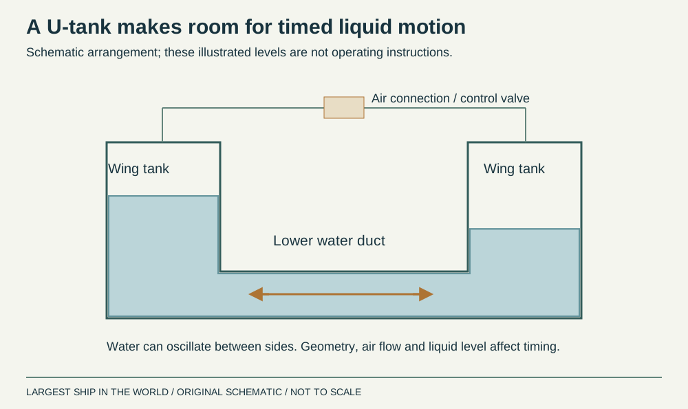
An anti-roll tank uses liquid moving across the vessel to create a moment that reduces rolling. Its geometry and liquid depth influence the timing of that movement. In a passive system, the ship’s own motion drives the fluid response; there is no requirement to pump the full liquid mass from side to side on every roll. The useful effect depends on phase, meaning the relationship in time between the ship’s motion and the tank’s response.
Hoppe describes its FLUME arrangement as an open-channel box tank whose natural response can be adjusted by changing liquid level. Monitoring the ship’s roll period helps match the tank to the operating condition. A pump used to adjust that level is performing a tuning task, which is different from continuously driving the oscillation. This distinction prevents a common misunderstanding: an anti-roll tank is not merely an ordinary ballast tank sloshing accidentally. Its layout and operating condition are deliberately engineered to produce a useful dynamic response.
Sources: [10] Hoppe Marine: FLUME tank operation and liquid-level tuning ↗
U-tanks, air control and anti-heeling
A U-tank connects tanks on opposite sides through a lower water passage. An air connection between their upper spaces, with suitable valves, can influence the liquid’s response. Hoppe’s INTERING description includes wing tanks, a lower duct, air-control arrangements and motion monitoring. It remains a passive roll-damping concept even though valves and monitoring can help manage its behaviour. An electrically supervised system is not necessarily one that actively pumps every roll cycle.
Anti-heeling is a related but distinct job. During loading, transferring cargo can cause a comparatively steady list; an anti-heeling system compensates for that imbalance. Roll damping deals with repeated oscillation at sea. Some installations share tanks for both functions, but their operating objectives differ. Trying to understand them as the same process obscures why timing is central to one and longer-term weight balance to the other. Tank capacity alone therefore says little about the quality of an anti-roll installation.
Sources: [11] Hoppe Marine: INTERING U-tank roll damping ↗
Why uncontrolled sloshing can make matters worse
Liquid in a partly filled tank moves as the ship heels. Its changing distribution reduces the available restoring effect, commonly described as a free-surface correction to stability. Wide slack tanks can be particularly consequential. The existence of engineered anti-roll tanks does not make this ordinary free-surface effect disappear. Their intended dynamic benefit must be considered alongside the stability consequences of the liquid and its location.
That is why adding a partly filled tank is not a general recipe for a smoother ship. A useful installation needs the appropriate layout, tuning, structural arrangement and loading assessment. Poorly matched liquid motion can fail to deliver the intended damping, while the free surface still affects stability. The apparent contradiction is resolved by separating two questions: what does the tank do to the vessel’s restoring characteristics, and what moment does its moving liquid generate during the roll cycle? A naval architect has to account for both rather than assuming one cancels the other.
Sources: [12] Wärtsilä: free-surface effect ↗
Gyroscopes: a spinning flywheel inside the vessel
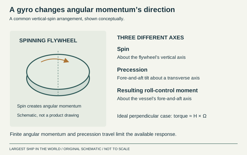
A gyroscopic stabilizer contains a rapidly spinning flywheel mounted so its orientation can change about another axis. This controlled tilting is called precession. Changing the direction of the flywheel’s angular momentum involves torque; the reaction is transmitted through the installation to the vessel. With the appropriate arrangement and control, that torque reduces rolling. The gyro does not need an external fin or forward water flow to generate its stabilizing moment.
Seakeeper’s explanation describes a flywheel within a vacuum enclosure and fore-and-aft precession in response to roll. The linked video focuses on small boats, making the principle visible without implying that the same unit would suit a cruise ship. The vessel still needs a suitable foundation, power and the services required by its installation. A spinning flywheel is also not a permanently fixed reference that makes the hull immovable. Its permitted precession and control determine how its angular momentum can be used, and the available stabilizing response is finite.
Sources: [13] Seakeeper: how its gyroscopic stabilizer works ↗
Gyro sizing: torque is not the whole story
Angular momentum and torque are different quantities. Angular momentum describes the flywheel’s rotational state; torque describes how rapidly angular momentum changes. In an ideal perpendicular-axis example, gyro torque is approximately H × Ω, where H is flywheel angular momentum and Ω is precession rate. An illustrative H of 6,000 newton-metre-seconds at 0.5 radians per second gives about 3,000 newton-metres. These inputs are a teaching example, not a vessel-sizing recommendation.
Seakeeper cautions against comparing gyros only by peak torque. Faster precession can generate a larger moment, but it consumes available precession travel more quickly, limiting how long that output can be sustained. Roll period therefore matters as well as peak force. A system must manage repeated cycles, not just one impressive instant. For readers evaluating a product claim, ask for angular momentum, usable torque over time and the test vessel’s conditions. A headline torque figure cannot by itself establish the reduction in roll experienced during a real passage.
Sources: [14] Seakeeper: angular momentum versus maximum torque ↗
Choosing a system for the ship’s working life
The operating profile helps narrow the choice. A vessel spending long passages at speed presents a different problem from one spending hours stationary at an offshore site. A tank arrangement uses internal volume and carries liquid mass. A gyro needs an internal installation and foundation. Fins occupy space outside the hull when deployed and need supporting equipment inside. Passive bilge keels contribute damping without an active control loop. These trade-offs explain why combinations can be useful.
There are also less familiar approaches. Rudder roll stabilization uses controlled rudder movement to generate a counteracting roll moment while still meeting the steering task. Wärtsilä notes that this increases loading on the rudder and steering gear. It is an engineered control application, not a reason to weave a ship from side to side. The right solution is therefore selected with the complete vessel in mind: geometry, duty cycle, space, power, steering, maintainability and the motions that matter to its passengers or work.
Weather, heading and parametric rolling
Operating choices remain important even with stabilizers running. The ship’s speed and direction influence the waves it encounters, and the bridge team considers those relationships alongside navigation and the vessel’s operating guidance. There is no universally safe instruction to turn every ship into the waves or always slow to the same speed. IMO’s adverse-weather guidance describes several dangerous motion phenomena requiring ship-specific judgement.
Parametric rolling is different from a simple wave pushing directly from the side. Passing waves can periodically change the hull’s immersed geometry and restoring characteristics. Under suitable timing relationships, that variation can build substantial rolling, including in head or following seas. ITTC treats prediction of this phenomenon as a specialised assessment problem. A comfortable response in one test condition does not demonstrate protection against every such mechanism. Stabilizers add control authority; they do not remove the need to understand the ship’s vulnerability, monitor conditions or make appropriate operational decisions.
Sources: [16] IMO: guidance on adverse weather and sea conditions, MSC.1/Circ.1228 ↗ [17] ITTC: predicting parametric rolling, 2024 procedure ↗
What passengers feel: angle, period and acceleration
The size of the roll angle is only part of the experience. A slow movement and a quick movement through the same angle produce different accelerations. Position aboard also matters: points farther from a rotation axis move through a longer arc for a given angle. Pitch and heave add their own contributions, so a roll measurement alone cannot fully describe comfort throughout the vessel. MARIN evaluates motion experience using numerical predictions, model-test information and facilities that reproduce motion.
For a simple geometric illustration, a point 10 metres above a fixed roll axis moves sideways by about 0.87 metre at 5 degrees of roll. At 20 metres above that axis, the corresponding movement is about 1.74 metres. This is an isolated roll calculation, using height multiplied by the sine of the angle. A real ship also translates and rotates in other ways. The example explains why controlling angular motion matters across the ship without pretending that one location or one stabilizer setting eliminates all discomfort.
How engineers establish whether it works
A credible performance comparison defines the vessel, loading condition, speed, wave conditions and measurement method. Roll reduction might refer to a typical statistical measure, such as root-mean-square angle, or to a peak value. Those are not interchangeable. A short clip showing one gentle interval with the system on and a rougher interval with it off does not establish a like-for-like saving.
Suppose an explicitly hypothetical test reduces RMS roll from 4 degrees to 1 degree under comparable conditions. The reduction in that metric is (4 − 1) ÷ 4 = 75%. This does not promise that the largest roll will also fall by 75%, or that another sea state will yield the same result. Engineers combine controlled testing with analysis to understand the response. ITTC’s roll-damping procedure describes experimental and analytical approaches, including decay testing. The practical question is whether the measured improvement persists across the operating conditions important to this particular ship, with uncertainties and system limits made clear.
Sources: [4] ITTC: estimation of roll damping, 2021 procedure ↗
What happens when the system reaches its limits?
Fins can reach their available angle, speed or load; tank response can become less effective away from its intended tuning; a gyro has finite angular momentum and precession travel. Active installations also rely on their power and control arrangements. Quantum’s hydraulic-system descriptions illustrate the supporting machinery needed to turn a commanded stabilizing action into movement. A fin visible outside the hull is only the final part of that chain.
If equipment is unavailable or limited, the ship’s motion can increase and its operating choices may need to change. That does not mean its underlying restoring stability has suddenly been created or removed by the stabilizer switch. The two functions remain distinct. Keeping a ship comfortable is a continuing engineering task involving a sound hull, appropriate loading, damping devices, effective controls and competent operation. Together they reduce the roll people feel and the motion equipment must endure. They work with the vessel’s dynamics rather than holding a vast steel ship rigidly still in a moving sea.
Watch the engineering in action
Sources & further reading
An editorial explainer based on the technical, research and industry references below.
- Wärtsilä: roll stabilisation ↗
- Wärtsilä: ship motions ↗
- Wärtsilä: metacentric height ↗
- ITTC: estimation of roll damping, 2021 procedure ↗
- Wärtsilä: bilge keels ↗
- Kongsberg Maritime: fin stabilisers ↗
- NASA Glenn: the lift equation ↗
- Quantum: stabilizer control systems ↗
- Kongsberg Maritime: stabilisation at rest ↗
- Hoppe Marine: FLUME tank operation and liquid-level tuning ↗
- Hoppe Marine: INTERING U-tank roll damping ↗
- Wärtsilä: free-surface effect ↗
- Seakeeper: how its gyroscopic stabilizer works ↗
- Seakeeper: angular momentum versus maximum torque ↗
- Wärtsilä: rudder roll stabilisation ↗
- IMO: guidance on adverse weather and sea conditions, MSC.1/Circ.1228 ↗
- ITTC: predicting parametric rolling, 2024 procedure ↗
- MARIN: assessing ship motions and comfort ↗
- Quantum: stabilizer hydraulic systems ↗