Raising Costa Concordia: parbuckling, sponsons and the engineering of recovery
How engineers stabilized, rotated and refloated a damaged passenger ship, and why supporting the wreck was as important as applying the force to move it.
By Largest Ship in the World · 11 min read · Published
More in ENGINEERING CASE STUDY →Running a giant series →Try the engineering lab →
Contents · 15 sections
An engineering story with a human starting point
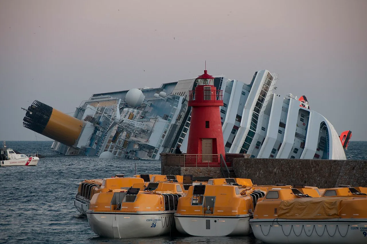
Costa Concordia was lost off Giglio in January 2012. The disaster was a human tragedy before it became a landmark salvage project. The work that followed had to address a damaged passenger ship lying on its side, the surrounding coastal environment and a difficult physical setting. Recovering such a wreck involves a different problem from repairing a normally floating vessel in a sheltered berth.
This case study follows the recovery principles rather than retelling the bridge decisions that led to the casualty. Official emergency material and accounts from the project participants provide the chronology and method. The diagrams are original educational schematics. They show how support, rotation and buoyancy interact without pretending to reproduce the project’s calculations or construction drawings. That distinction matters because the operation depended on a detailed understanding of the actual wreck, seabed and damaged structure.
Sources: [1] Italian Civil Protection: Concordia emergency, 2012–2014 ↗

The first problem was keeping the wreck controlled
A ship lying against an uneven seabed can be supported at concentrated areas rather than along the distribution for which it was designed. Its position may also be vulnerable to further movement. Crowley’s account describes the wreck resting on underwater rock features. The anchoring and stabilization work therefore belonged at the start of the recovery, before the visually dramatic rotation.
This reverses a common way of imagining salvage. The first question is not always how to lift the object. It can be how to prevent unwanted movement while gaining enough information and creating a controlled working arrangement. Surveying, structural assessment and geotechnical work contribute to that answer. A seabed is not an abstract fixed point in a diagram: the material and geometry determine how anchors, piles and support structures transfer their loads into the ground.
Sources: [2] Crowley / TITAN: Raising the Costa Concordia ↗ [6] ISSMGE: technical paper on Costa Concordia anchoring ↗
Parbuckling means rotating, not lifting vertically
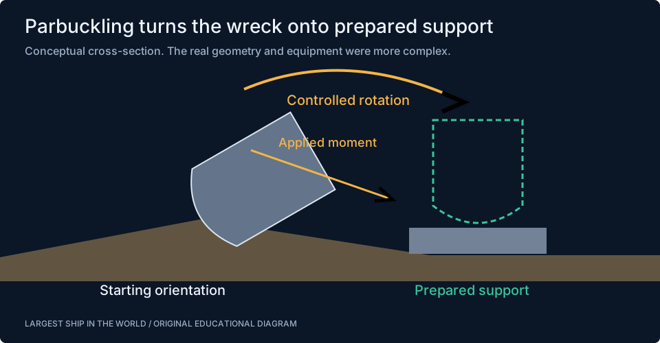
Parbuckling turns an object by applying a controlled moment. In the ship-recovery context, the intention was to bring the hull from its heeled resting position towards upright. That is mechanically different from attaching a vertical crane hook and lifting the entire wreck clear of the sea. The rotation changes the positions of the ship’s mass, its contact areas and the forces in the recovery system throughout the movement.
A barrel rolled with a rope offers a simple conceptual analogy, but a damaged ship cannot be treated as a rigid cylinder. Its shape is irregular, its structure has been damaged and its interaction with water and ground changes as it rotates. The useful lesson from the analogy is the role of a moment arm: a force applied with leverage can produce rotation. The actual project required a coordinated system that maintained control as the geometry evolved.
Sources: [4] Italian Civil Protection: recovery planning, English publication ↗ [5] US Navy SUPSALV: Faceplate, November 2013 ↗
What the force diagram leaves out
A clean drawing might show a weight arrow, a cable force and a support reaction. Each represents something more complicated in the real wreck. Weight is distributed across hull, machinery, interiors and retained water. Cable forces enter through engineered connections. Contact with the seabed occurs over particular regions. The diagram helps organize the problem but does not determine any of those quantities.
For a purely illustrative calculation, a force of 1,000 kilonewtons acting with a perpendicular lever arm of 20 metres creates a moment of 20 million newton-metres. If the lever arm changes during rotation, the same force creates a different moment. This is one reason control cannot rely on a single fixed pull throughout the motion. The numbers are an original teaching example, not reported loads from the Costa Concordia project. Actual design required the changing geometry and structural capacity to be considered together.
Prepared support gives the rotation a destination
The recovery plan included preparing support for the wreck after it was brought upright. That step is easy to overlook because the moving ship attracts attention, but it defines where the load will go at the end of rotation. Reaching an upright attitude without a suitable support condition would merely exchange one unstable problem for another.
Think of rotating a heavy cabinet onto its base. The final surface must support it, and its route to that surface must be clear. The ship-scale problem adds underwater construction, irregular rock and a damaged hull, so the analogy is limited to the basic logic. The prepared seabed arrangement, stabilization and pulling system are parts of one sequence. Their design must agree about the wreck’s intended position and the forces expected as support transfers from one part of the system to another.
Sources: [2] Crowley / TITAN: Raising the Costa Concordia ↗ [4] Italian Civil Protection: recovery planning, English publication ↗
Strand jacks make large controlled movements possible
A strand-jack system uses hydraulic action and gripping arrangements to move a load along steel strands in controlled increments. The mechanism provides a way to apply substantial force while managing displacement. In a coordinated lifting or pulling operation, the issue is not simply that each unit can exert a large force; their combined action must achieve the intended motion without introducing an unacceptable imbalance.
Measurements and control therefore matter alongside nominal capacity. A system needs to respond to the actual behaviour of the load and its supports. The principle is similar to carrying a long object with several people: unequal movement can twist the object even if everyone is individually strong enough. The real recovery involved engineered equipment and monitoring at a completely different scale, but the comparison explains why synchronization and load distribution are central engineering concerns.
Rotation changes several things at once
As a heeled hull moves towards upright, its immersed shape changes. Water may occupy damaged spaces differently, and the position of structural elements relative to the seabed changes. The centre of mass and the effective buoyant contribution must be considered within that evolving geometry. A static calculation at the beginning cannot describe the complete motion without accounting for those changes.
That makes recovery a sequence problem. Engineers need to understand the current state, the next intended state and the transition between them. The required forces can rise or fall as leverage and support change. A moment that assists rotation in one part of the movement can have a different significance later. Time-lapse footage compresses these changes into a short visual sequence, but the important engineering lies in preserving control through each stage rather than simply reaching the final angle.
Sponsons provide a new buoyancy system
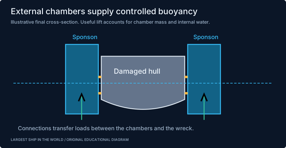
Large external chambers called sponsons formed a central part of the recovery arrangement. Attached to the wreck, they could contribute controlled ballast or buoyancy as the project moved through its stages. Once the ship was upright and prepared for refloating, the added chambers helped provide flotation that the damaged hull alone could not simply be assumed to supply.
Their function is easier to understand by separating shape from contents. An immersed chamber displaces water, while water retained inside contributes weight. Removing internal water changes the net upward contribution, subject to the chamber’s geometry and conditions. This is the same underlying buoyancy principle discussed in the ballast guide, used here in a very different situation. The sponsons were not decorative floats tied to railings. Their loads had to pass through purpose-designed connections into a structure whose condition required careful assessment.
Sources: [3] Micoperi: salvage ↗ [4] Italian Civil Protection: recovery planning, English publication ↗
A buoyancy calculation that shows the scale
Suppose an illustrative chamber has 1,000 cubic metres of effective immersed volume. In seawater of assumed density 1.025 tonnes per cubic metre, that volume corresponds to a gross buoyant contribution of 1,025 tonnes. The chamber’s own mass and anything carried within it must be accounted for before calling the difference useful lift. The calculation also changes if the chamber is only partly immersed.
This simple example demonstrates why describing a sponson only by its external dimensions is incomplete. Its weight, internal water, immersion and connection loads all matter. A group of chambers also needs to be balanced around the casualty. More buoyancy at one end or side changes attitude rather than merely lifting the whole object evenly. These are educational calculations, not estimates of Costa Concordia’s actual sponson capacities. The project-specific values belong to the engineering records of the recovery.
Righting is different from refloating
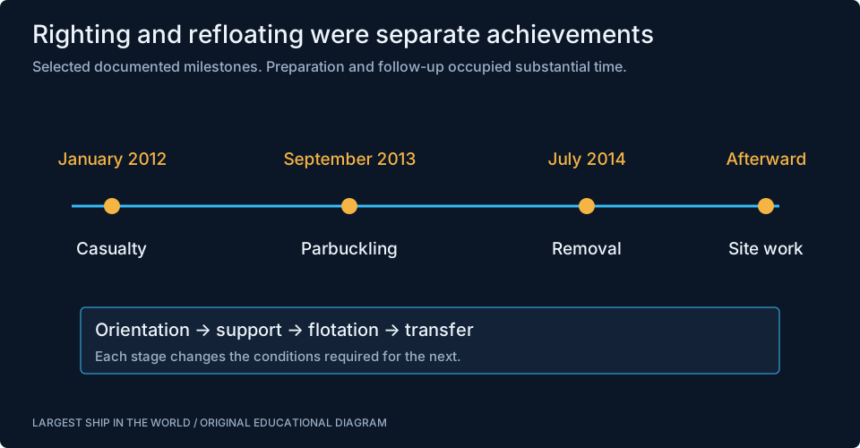
The wreck was brought upright in September 2013. Removal from Giglio followed in July 2014. Those distinct milestones show that a successfully righted hull was not immediately ready to leave. Further work was needed to prepare the flotation arrangement and the vessel for its final transfer. A timeline that merges the two events hides a substantial part of the engineering.
The distinction is physical. Upright describes orientation. Afloat describes how the object is supported. Ready for tow adds another set of requirements concerning integrity, stability, control and the planned journey. None of those states automatically proves the next. This is a useful pattern for understanding other maritime projects too: launching a new hull does not mean delivery, and recovering a casualty’s buoyancy does not mean restoration to passenger service. The next operation imposes its own conditions.
Sources: [1] Italian Civil Protection: Concordia emergency, 2012–2014 ↗ [2] Crowley / TITAN: Raising the Costa Concordia ↗
The operation had distinct milestones
The broad sequence begins with the January 2012 casualty and the emergency response. Stabilization and recovery preparation followed. Parbuckling in September 2013 brought the hull upright; the subsequent programme prepared it for refloating and removal in July 2014. The final transfer to Genoa was followed by dismantling and continued work associated with the original site.
These selected stages are the framework shown in our timeline. They are intentionally not a minute-by-minute operational log. Each stage contains design, procurement, construction, checking and coordination that a simple date cannot express. Reading the timeline alongside the force and buoyancy diagrams makes the sequence meaningful: first establish control, then change orientation, then establish flotation and transfer capability. The dates document progress, while the engineering explains why one milestone could not simply be skipped to reach the next.
Sources: [1] Italian Civil Protection: Concordia emergency, 2012–2014 ↗ [8] Italian Civil Protection: closure and site-restoration context ↗
A tow is another engineering state
Once a wreck is afloat, it must still withstand the conditions of a transfer. Tow forces, weather, movement and the behaviour of the added flotation system need to be considered. The tow arrangement and supporting vessels are part of that plan. A short distance on a regional map can still represent a demanding operation for a damaged ship with an unusual external structure.
The general principle is that design loads depend on the activity. A connection adequate for one controlled stage cannot be assumed adequate for every later stage without assessment. Similarly, a stable condition in sheltered water does not describe every wave encounter. This article does not reconstruct the project’s weather criteria or tow calculations from public photographs. It explains why the move to Genoa was a planned phase of the recovery, with its own engineering questions rather than a routine departure after the main work ended.
Environmental work continues after the ship leaves
Removing a wreck is only one part of addressing its effect on a coastal site. Work can also involve monitoring, managing material released or disturbed, and restoring areas used by the recovery operation. The official Civil Protection material describes the continuing context of dismantling and site work. A ship no longer visible from the shore does not mean that every consequence has ended.
This broader boundary matters when evaluating a salvage project. The visible lifting or rotation can dominate the story, while the preparation and follow-up carry much of the environmental effort. A useful account keeps all those stages in view. It also avoids assuming that one yard or method applies to every ship’s final chapter. Costa Concordia’s transfer to Genoa belongs to its specific history; ordinary ship recycling at places such as Aliağa or Alang involves different vessels, conditions and documented arrangements.
Sources: [4] Italian Civil Protection: recovery planning, English publication ↗ [8] Italian Civil Protection: closure and site-restoration context ↗
What the photographs can and cannot establish
The gallery shows Costa Concordia in service and later lying on its side near Giglio. Together, the photographs make the change in orientation and condition immediately understandable. They also show the scale relative to lifeboats and harbour structures. That is valuable visual evidence without requiring an invented numerical claim about loads or residual strength.
The underwater support arrangement, damaged internal compartments and full sponson connection details are not visible in those views. Our diagrams supply a conceptual explanation, explicitly labeled as schematic, while the linked official and contractor sources supply the project context. This combination is stronger than presenting a photorealistic invented cutaway as a construction record. It lets readers distinguish observation, documented history and educational interpretation, all of which have different roles in understanding a complex engineering operation.
Why this case is worth studying
The Costa Concordia recovery shows how engineering can create a new support and flotation system around a damaged structure. Anchoring controlled unwanted movement. Prepared support gave rotation a destination. Pulling equipment supplied controlled moments. Sponsons provided a path towards flotation, and the transfer plan carried that condition into the next stage. The work depended on those parts fitting together through time.
Compare it with Ever Given’s refloating. Both involved buoyancy, external forces and structural constraints, but their dominant physical problems were different. One required clearing and releasing a grounded operating ship in a canal; the other required recovering a heavily heeled wreck for removal. The comparison helps explain why salvage is not a collection of interchangeable tricks. Each project starts with evidence about the actual casualty and builds a sequence of controlled states around the conditions it finds.
Watch the engineering in action
Sources & further reading
An editorial explainer based on the technical, research and industry references below.
- Italian Civil Protection: Concordia emergency, 2012–2014 ↗
- Crowley / TITAN: Raising the Costa Concordia ↗
- Micoperi: salvage ↗
- Italian Civil Protection: recovery planning, English publication ↗
- US Navy SUPSALV: Faceplate, November 2013 ↗
- ISSMGE: technical paper on Costa Concordia anchoring ↗
- Smithsonian: Costa Concordia recovery film ↗
- Italian Civil Protection: closure and site-restoration context ↗