How ship ballast systems work: tanks, trim, stability and treatment
Why ships carry seawater, how crews move it through the hull, and why stability, structural strength and biological treatment are different parts of the same operation.
By Largest Ship in the World · 11 min read · Published
More in BALLAST & STABILITY →Running a giant series →Try the engineering lab →
Contents · 15 sections
Why an almost empty ship still needs weight
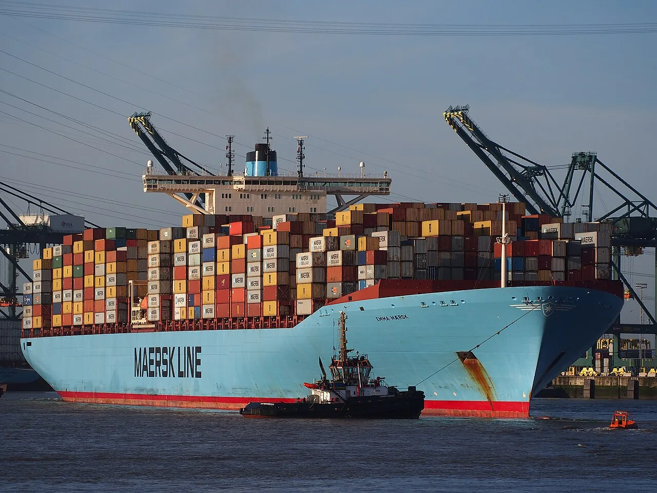
A cargo vessel is designed to operate through changing loading conditions. It may arrive with heavy cargo and leave after discharging it, while fuel and freshwater are consumed throughout a passage. These changes alter how deeply the hull sits, the immersion of its propeller and its balance. Ballast water provides controllable weight that can help achieve an appropriate condition for the next stage of the operation.
That does not mean an empty ship should be filled with as much water as possible. Extra mass increases displacement and can increase resistance. More draft can reduce under-keel clearance. The distribution of ballast affects bending loads as well as the ship’s attitude. The objective is a suitable complete loading condition, using the vessel’s approved information. Ballast is one tool within that calculation, alongside cargo distribution, consumables, strength limits and the conditions expected on the voyage.
Sources: [1] IMO: ballast water management ↗
_IMO_9321483_Schelde_Port_of_Antwerp_pic5.JPG)
Four quantities that are often confused
Draft is the vertical distance between the waterline and the bottom reference of the hull. Trim describes the difference between forward and aft drafts. List is a persistent sideways inclination caused by an unequal distribution of weight or other sustained effects. Stability concerns the moments that develop when a ship is inclined and its tendency to return or move farther from equilibrium. A vessel can have acceptable-looking trim while still having an unsuitable stability condition.
The distinction matters when looking at photographs. A tanker sitting high in the water is not necessarily unstable; it may simply be lightly loaded. A ship leaning to one side is not necessarily rolling at that instant. A low bow can reflect trim rather than a wave passing underneath it. Ballast operations can influence all these quantities, but the effects are not interchangeable. The ship needs a loading calculation, not a visual judgement based on whether its deck appears level.
Where the water goes
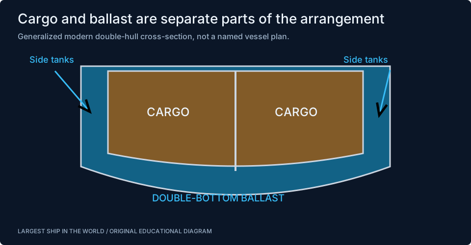
Ballast can occupy tanks in the double bottom, side spaces and forepeak or afterpeak, depending on the ship. On a modern double-hull tanker, spaces separating the cargo region from the outer shell can have a ballast function as well as contributing to the overall arrangement. Container ships and bulk carriers use arrangements suited to their holds, machinery and structure. There is no universal set of tanks shared by every large vessel.
Compartment location is important because each tonne contributes both weight and a moment about a reference point. Water low in the hull has a different vertical effect from the same water high in a side tank. Weight near the bow has a different trim effect from weight amidships. Two ships with the same total ballast quantity can therefore have different loading conditions. A tank diagram becomes useful only when its locations, capacities and actual contents are understood together.
Sources: [2] Wärtsilä: ballast system ↗
A transparent buoyancy example
Imagine a rectangular barge 200 metres long and 32 metres wide in seawater with an assumed density of 1.025 tonnes per cubic metre. Its waterplane area is 6,400 square metres. In this deliberately simple geometry, adding 6,560 tonnes evenly would increase draft by one metre: the extra displaced volume is the added mass divided by water density. The calculation demonstrates Archimedes’ principle without requiring a detailed hull model.
A real ship does not have a rectangular immersed shape, and its waterplane area can change with draft. Naval architects use hydrostatic data to relate displacement and immersion for the actual hull. Our interactive ballast model deliberately uses the barge assumption, displays it and excludes stability and strength predictions. Moving a slider can reveal the direction of an effect, but its numerical result is not a draft forecast for any of the named vessels in the directory.
Moving weight changes trim
Adding ballast near the bow produces a forward trimming moment; adding it near the stern produces an aft moment. Transferring water from one end to the other can change trim while leaving total displacement approximately unchanged. Taking water from the sea changes both displacement and its distribution. Those two operations may look similar on a tank display, yet they do not have the same effect on the mean waterline.
For a basic moment comparison, 1,000 tonnes placed 50 metres forward of a chosen reference has a moment of 50,000 tonne-metres about that reference. Place the same mass five metres away and its moment is ten times smaller. Converting that moment into actual trim requires the hull’s longitudinal hydrostatic properties. The arithmetic explains why the location of a tank matters; it does not tell an operator which tank to use or establish whether the resulting condition meets the ship’s limits.
Follow a ballast-water transfer
A ballast system connects the sea, tanks, pumps and discharge arrangements through piping and valves. Its exact layout determines which transfers are possible. A pump creates the pressure difference needed to move water, while tank levels and valve positions help the crew monitor the operation. The same pipework cannot be assumed to connect every tank directly to every other tank in every vessel.
Near the end of emptying, a system faces different conditions from those at a comfortably flooded pump suction. Tank geometry, trapped liquid and the pump’s ability to maintain suction all affect how much water remains. This is one reason the words empty and full on a schematic deserve care. They can describe an operational state rather than a perfect mathematical absence or complete filling of every void. Residual water and sediment also connect the hydraulic operation to maintenance and environmental management.
Sources: [2] Wärtsilä: ballast system ↗ [3] Wärtsilä: ballast pumps ↗
Cargo work and ballast work have to agree
A ship can experience its most demanding weight changes while alongside. Cargo may be removed from one hold before another, or heavy units may be placed in a particular sequence. Ballast adjustments must be coordinated with that progression. A satisfactory final loading condition does not prove that every intermediate stage is satisfactory. The hull passes through a sequence of weight distributions while shore equipment and onboard pumps work at different rates.
Think of a long shelf supported by water along its length, with cargo concentrated at selected positions. Removing weight from the middle before the ends changes the bending pattern. Ballast provides another distribution of weight, but its placement cannot be judged independently from the cargo. Real loading instruments use the vessel’s approved structural and hydrostatic information. The educational lesson is that timing and sequence matter, not only the totals recorded after loading has finished.
The free-surface effect
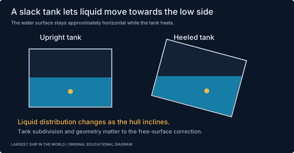
Liquid in a partly filled tank can move as the hull inclines. Its surface tends towards horizontal, shifting the liquid’s centre of gravity towards the low side. This reduces the ship’s initial stability compared with treating the same liquid as a fixed solid weight. A slack tank is therefore more complicated than a block of ballast rigidly attached to the hull.
Tank width and subdivision influence the free-surface contribution. Simply knowing the percentage filled is not enough to calculate it. Several partly filled tanks can have a combined effect that matters to the loading condition. Purpose-designed anti-roll tanks use controlled fluid motion to reduce rolling, but ordinary ballast tanks should not be mistaken for those devices. The illustrated comparison explains the mechanism only. The stability calculation belongs to the actual vessel, with its tank geometry, contents and approved corrections.
Sources: [4] Wärtsilä: free-surface effect ↗
More initial stability is not automatically more comfort
Stability and motion are connected but are not the same design target. A vessel with a stronger small-angle restoring response can have a shorter natural roll period, while a different loading condition may produce slower motion. Wave encounter, damping and the distribution of mass also contribute. Making a ship feel less lively is not a sufficient basis for adjusting its loading, because adequate stability and other limits remain essential.
This is why the ballast demonstration and rolling demonstration on this site are separate models. One shows longitudinal weight distribution using a barge geometry. The other shows resonance and damping in a simplified oscillator. Connecting them into an apparently realistic ship simulator would require many more inputs and a validated hydrodynamic model. Keeping their assumptions visible helps readers understand each mechanism without suggesting that a comfort slider can replace a loading instrument or stability booklet.
Sources: [8] IMO: ship design and stability ↗
Ballast can transport living organisms
Seawater is not biologically empty. Water taken aboard can contain organisms that survive the voyage and enter a different environment when discharged. Some can establish populations with damaging ecological consequences. This is the central problem addressed by international ballast-water management: the operation that helps a ship maintain its loading condition can also move life between regions.
The environmental question is different from the buoyancy calculation. Water can be in the right tank and contribute exactly the intended weight while still requiring treatment or other approved management before discharge. Conversely, successful biological treatment does not establish that the ship’s draft or stability is suitable. A complete explanation of ballast therefore needs both naval architecture and water management. Treating one as a footnote to the other misses why the machinery, documentation and operating sequence have become so closely connected.
Sources: [1] IMO: ballast water management ↗
How a UV-based treatment system works
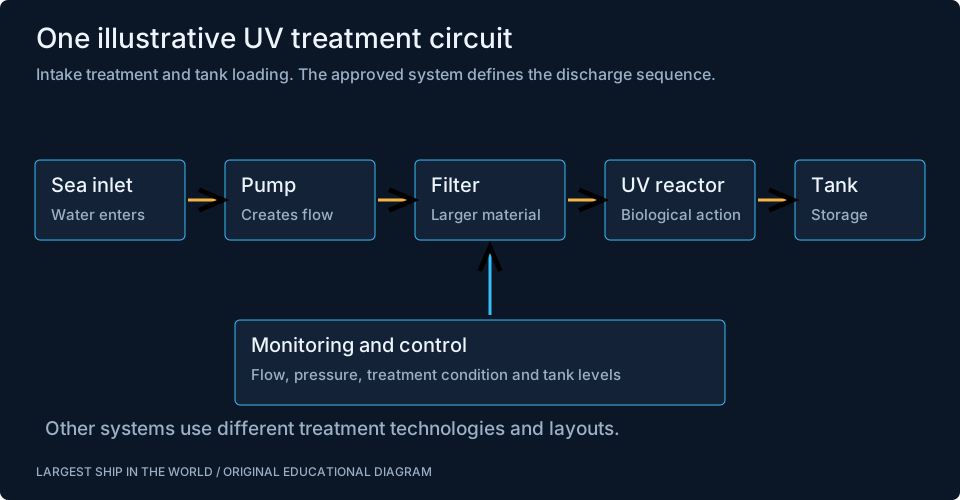
One common treatment approach combines filtration with ultraviolet light. The filter removes larger material, while a UV reactor exposes the flowing water to radiation intended to inactivate organisms. The reactor’s performance depends on the installation and its operating conditions, including water quality and flow. A simplified animation can make this process look like a short pipe with a lamp, but the real system also needs sensors, controls and maintenance access.
Alfa Laval’s PureBallast is an example of this technology family, and the linked video illustrates its components. Manufacturer performance claims apply to the specified product and approval envelope. They should not be generalized to every UV installation. Filtration and treatment also affect power demand and the time available for a ballast operation. The resulting plant must fit within the ship’s hydraulic system and its operating schedule, not merely occupy an empty patch of machinery-space floor.
Sources: [5] Alfa Laval: PureBallast 3 ↗
Other treatment approaches and their tradeoffs
Electrochlorination is another approach used in ballast-water treatment. It uses electrochemical processes to produce an active disinfectant, with associated monitoring and handling requirements. Water properties, system design and any necessary neutralization are part of its operating context. UV and electrochlorination are therefore different technical pathways rather than two interchangeable boxes carrying the same label.
Selecting a system involves the ship’s flow requirements, power availability, space, routes and expected water conditions. Installation work also includes pipe routing, structural foundations, controls and commissioning. A treatment unit that can process a nominal flow in a brochure still has to operate within the actual system’s pressure and water-quality limits. The useful question for a retrofit is how the whole arrangement behaves during the ship’s real port operations, including awkward conditions and maintenance periods.
Sources: [7] Wärtsilä: UV and electrochlorination treatment options ↗
What management standards describe
IMO distinguishes the D-1 exchange standard from the D-2 discharge-performance standard. Exchange concerns replacement of ballast water, while the performance standard concerns the organisms allowed in discharged water. The Convention also provides a framework for management plans, records, approval and implementation. These are different requirements with different purposes, so the presence of a treatment unit alone should not be described as proof of complete compliance.
The linked IMO material is the appropriate starting point for understanding that framework. A particular ship’s obligations depend on the applicable rules, administration and circumstances, and can change as requirements develop. This article explains the engineering context rather than presenting a checklist for discharging water. The durable distinction is between the physical ballast operation, the biological treatment process and the records needed to demonstrate what happened. Each must be understood on its own terms and connected to the others.
Sources: [6] IMO: implementing the Ballast Water Management Convention ↗
Why sensors and records matter
A control screen is a representation of a physical system. Tank level, valve position, pressure and flow data help operators understand it, but a plausible-looking display is not the same as independent confirmation of every condition. Sensor checks, maintenance and attention to unusual trends are part of keeping that representation useful. A slowly changing level might reflect the intended transfer, an unexpected restriction or an instrument problem.
Records make the operation traceable across watches and voyages. They connect where water was taken aboard, what management occurred and what was later discharged. They also help distinguish normal changes from unexplained losses or gains. For an engineering reader, the key point is that the ballast system extends beyond tanks and pumps. It includes information: measurements, planned sequences, crew communication and a record of events. Those parts determine whether the physical equipment can be used coherently.
What to notice in the cutaway
Return to the tanker or container-ship drawing and look for the low tanks, long cargo spaces and machinery near the stern. Consider how removing cargo changes the mass distribution, then imagine adding water forward or aft. Next, notice what the drawing cannot tell you: tank capacity, actual filling level, structural limits and stability margins. A useful cutaway reveals relationships without pretending to be an approved loading plan.
The interactive lab makes two experiments easy. Add equal ballast at both ends and watch the mean draft rise. Then hold total ballast constant while moving it from aft to forward and watch trim change. Those simple effects are the beginning of the subject. The free-surface diagram, treatment circuit and full loading discussion explain why real operations require a much richer model of the ship. Ballast is ordinary seawater performing a carefully controlled engineering job.
Watch the engineering in action
Sources & further reading
An editorial explainer based on the technical, research and industry references below.