The 400-metre ceiling: why container ships stopped growing longer
The world largest container ships carry over 24,000 TEU, yet virtually none exceed 400 metres in length. Here is the engineering behind the 400-metre barrier, from hull girder bending and open-deck torsion to the beam expansion that reshaped global shipping.
By Alykhan Virani · 7 min read · Published
More in Shipbuilding →Running a giant series →Try the engineering lab →
Contents · 7 sections
The 400-metre barrier that defined an industry
Walk along the quay at Rotterdam, Antwerp, Singapore or Ningbo, and you will notice a striking consistency across the giants of maritime trade. The world premier container ships, from the 20,000-TEU pioneers to the latest 24,346-TEU flagship MSC Irina, share almost identical overall lengths. Virtually every mega-max container vessel afloat measures between 399.8 and 400.0 metres from bow to stern.
This is not a coincidence, nor is it an arbitrary round number chosen by shipping marketing executives. In an industry where transport economics relentlessly rewards economies of scale, naval architects pushed container ship lengths outward at an astonishing rate for three decades, expanding from 200 metres in the 1970s to 300 metres in the 1990s, and leaping to 397 metres with Emma Maersk in 2006. Yet for twenty years since that milestone, the length progression abruptly stopped. The ships grew dramatically larger, nearly doubling their container capacity from 15,000 to over 24,000 TEU, but they did not grow longer.
To understand why this invisible ceiling exists, one must look beneath the stacks of colourful steel boxes and examine the intense structural physics of the open ocean, the tight physical geometry of canal transit channels, and the commercial engineering of port container cranes.
Sources: [1] International Association of Classification Societies: Unified Requirements for Longitudinal Strength ↗ [2] Port of Rotterdam: Quay Wall Specifications and Container Crane Clearances ↗
The hull as a flexible beam: hogging and sagging in open water
At 400 metres in length, a modern container ship is longer than the Empire State Building is tall. Yet in the open sea, an ocean vessel cannot be built as an unyielding, rigid steel monument. It acts as an elastic hull girder, bending and flexing in response to moving swells and changing cargo distributions.
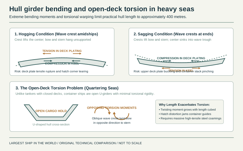
When navigating open waters, two primary longitudinal bending conditions govern the design of the hull. The first is hogging, which occurs when a long ocean wave crest lifts the ship under its middle, leaving both the bow and stern suspended over troughs with minimal water support. Under hogging, the vessel upper deck plating is stretched in severe tension, while the bottom keel structure is crushed in compression.
The second condition is sagging, where wave crests support the bow and stern simultaneously, leaving the center of the ship over a deep wave trough. In sagging, the mechanical stresses invert: the upper deck suffers extreme compressive forces, while the bottom keel plating stretches in tension. The magnitude of these longitudinal bending moments does not scale linearly with ship length; it increases roughly with the square of the length multiplied by the beam. When a hull stretches from 300 to 400 metres, wave-induced bending moments nearly double, demanding vastly thicker steel plating and massive longitudinal stiffeners just to keep the vessel from snapping in half.
Sources: [1] International Association of Classification Societies: Unified Requirements for Longitudinal Strength ↗ [3] DNV Guidelines for Ultra Large Container Ships: Torsion, Whipping and Springing ↗
The open-box dilemma: torsion in oblique waves
While supertankers and bulk carriers also experience intense longitudinal bending, container ships face an engineering challenge unique to their commercial purpose: the open-deck torsion problem. A tanker is essentially a closed steel tube, with small access hatches punctuating a solid weather deck. This closed tubular geometry provides tremendous natural resistance to twisting forces.
Container ships, by contrast, are open U-shaped steel troughs. To allow dockside gantry cranes to drop 20-foot and 40-foot containers straight into cell guides deep inside the hull, almost the entire top deck must be cut away into massive rectangular hatch openings. An open U-shaped cross-section has only a tiny fraction of the torsional stiffness of a closed tube.
When a 400-metre container vessel encounters quartering seas, where long ocean waves strike the hull at an angle, the wave crest twists the forward section in one direction while an adjacent crest twists the aft section the other way. This torsional warping causes the rectangular hatch openings to distort diagonally into rhombuses. If hull twisting becomes too pronounced, heavy container stacks jam inside the internal cell guides, hatch covers pop open or shear off, and cyclic stress concentrations tear at the hatch corners. Counteracting this severe torsion on hulls longer than 400 metres would require steel plates so thick and heavy that the added hull weight would wipe out any extra cargo capacity.
Sources: [1] International Association of Classification Societies: Unified Requirements for Longitudinal Strength ↗ [3] DNV Guidelines for Ultra Large Container Ships: Torsion, Whipping and Springing ↗
Port geometry: cranes, berths and turning basins
Beyond the structural boundaries of naval architecture, container ships operate within the physical constraints of global civil infrastructure. A ship has no commercial value if it cannot dock safely, turn around inside protected harbour basins, or be reached by quayside cranes.
Most premier container terminals were planned around standard quay increments. A 400-metre container berth can accommodate one mega-max vessel or two 190-metre feeder ships. Extending ship length to 450 or 500 metres would cause massive operational headaches: a single ship would overhang standard berths, tie up two entire crane gangs, and block adjacent berths from serving arriving vessels.
Harbour manoeuvring presents an equally rigid physical barrier. In key transshipment hubs like Hamburg on the Elbe River, Felixstowe, or Shanghai, turning basins where tugboats swing massive ships around are tightly bounded by channel dredging limits and bedrock. A vessel over 400 metres in length would require dramatically expanded turning basins that would cost billions of dollars to dredge and maintain, while facing dangerous leeway drift during crosswinds.
Sources: [2] Port of Rotterdam: Quay Wall Specifications and Container Crane Clearances ↗ [4] Suez Canal Authority: Maximum Beam and Draft Permissible Dimensions ↗
Why widening won: from 13 to 24 container rows
Faced with the 400-metre length ceiling, ship designers recognized that the path to higher capacity lay in expanding the hull beam and stacking containers higher above the deck.
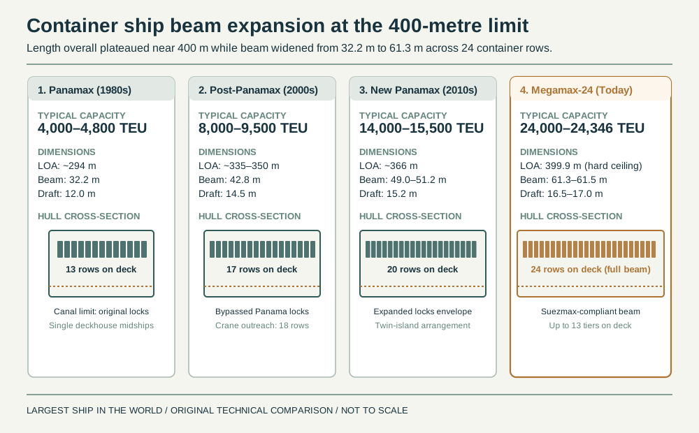
During the classic Panamax era, beam was strictly limited to 32.2 metres so ships could slide through the original 33.5-metre-wide locks of the Panama Canal, restricting deck arrangements to 13 container rows. Once shipping lines realized that Asia–Europe trade routes via the Suez Canal did not require Panama compliance, naval architects widened hulls first to 42.8 metres (17 rows), then to 49.0 metres (20 rows), and finally to 61.3 metres on today 24,000-TEU Megamax-24 designs, allowing 24 container rows across the weather deck.
Widening the beam provided multiple dramatic advantages. First, increasing beam provides huge increases in water displacement and deck surface area without lengthening the hull girder, keeping wave-bending moments within manageable structural limits. Second, a broader beam provides tremendous transverse stability, elevating the metacentric height (GM) and allowing operators to stack containers up to 13 tiers high on deck without endangering the vessel stability in rolling seas.
Sources: [2] Port of Rotterdam: Quay Wall Specifications and Container Crane Clearances ↗ [3] DNV Guidelines for Ultra Large Container Ships: Torsion, Whipping and Springing ↗
The split superstructure: separating bridge from engines
Stacking containers 13 tiers high on deck created another urgent operational problem: navigation visibility. Maritime safety rules enforced by the International Maritime Organization (IMO) mandate that the bridge watchkeepers must be able to see the surface of the sea within two ship lengths or 500 metres ahead of the bow, whichever is less.
On older container ships, the navigation bridge and accommodation block were placed directly above the engine room near the stern. But when deck stacks reached ten or twelve boxes high, a bridge located at the stern was completely blinded by a mountain of containers directly in front of the windows. Lengthening the bow forward to restore sightlines was ruled out by the 400-metre limit.
The breakthrough design solution was the twin-island arrangement. Naval architects physically severed the deckhouse from the engine room. They relocated the navigation bridge, ship offices and crew accommodations forward to the third or fourth cargo bay, while leaving the heavy main diesel engines, fuel tanks and exhaust funnels back near the stern. This split layout gave navigators an unobstructed view forward over lower forward container stacks, while opening up vast, uninterrupted deck space amidships for deep, high-density container stowage.
Sources: [1] International Association of Classification Societies: Unified Requirements for Longitudinal Strength ↗ [3] DNV Guidelines for Ultra Large Container Ships: Torsion, Whipping and Springing ↗
What comes next: fuel tanks and the limits of scale
Today, container ship design has reached a mature geometric equilibrium. At 399.9 metres long and 61.3 metres wide, a Megamax carrier matches the reach of the world largest ship-to-shore gantry cranes and the safe navigational tolerances of the Suez Canal.
Rather than chasing greater length, the next frontier of container ship engineering is focused on the energy transition. Traditional heavy fuel oil occupies relatively compact double-bottom tanks beneath the cargo holds. By contrast, alternative zero-carbon fuels such as liquefied natural gas (LNG), green methanol and liquid ammonia require insulated, pressurised or cryogenic fuel tanks that are three to four times larger for the same voyage range.
On modern dual-fuel giants like Hapag-Lloyd Berlin Express and CMA CGM Jacques Saade, massive 18,000-cubic-metre fuel tanks must be carved out directly from the cargo holds beneath the bridge deckhouse, sacrificing roughly 500 to 1,000 container slots. The engineering battle over the coming decade will not be about breaking the 400-metre ceiling, but about packing cleaner fuel systems, rotor sails, and shore-power connections into the existing, perfectly balanced 400-metre envelope.
Sources: [1] International Association of Classification Societies: Unified Requirements for Longitudinal Strength ↗ [4] Suez Canal Authority: Maximum Beam and Draft Permissible Dimensions ↗
Sources & further reading
An editorial explainer based on the technical, research and industry references below.
- International Association of Classification Societies: Unified Requirements for Longitudinal Strength ↗
- Port of Rotterdam: Quay Wall Specifications and Container Crane Clearances ↗
- DNV Guidelines for Ultra Large Container Ships: Torsion, Whipping and Springing ↗
- Suez Canal Authority: Maximum Beam and Draft Permissible Dimensions ↗