How a cruise ship is built: from steel blocks to a floating city
A cruise ship takes shape in sections. Understanding that process makes shipyard news much easier to follow.
By Alykhan Virani · 11 min read · Published
More in Shipbuilding →Running a giant series →Try the engineering lab →
Contents · 15 sections
A ship is an assembly project
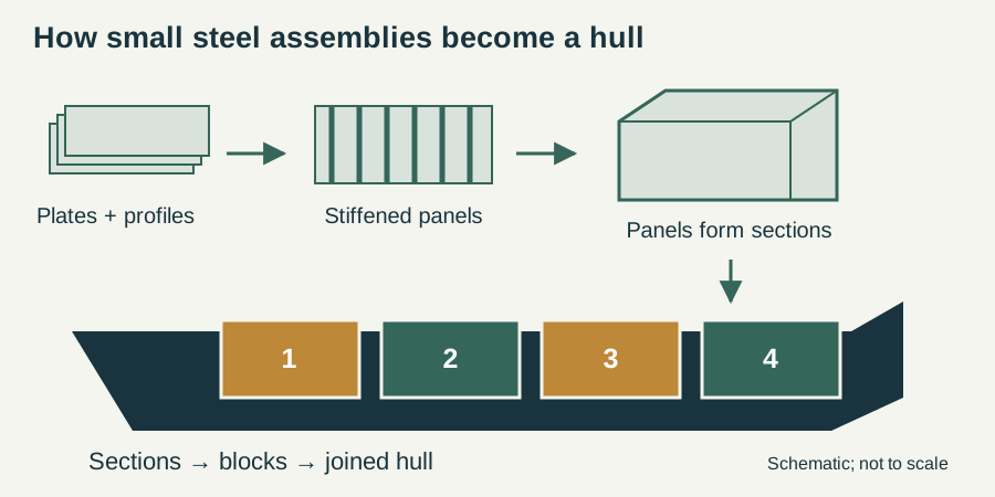
A cruise ship looks like one continuous structure from the quayside. During construction, however, it is a collection of smaller pieces that must come together in the right order. Meyer Werft describes its approach as modular construction: prefabricated blocks are joined into progressively larger units. That lets a yard organize work around manageable assemblies instead of treating the entire vessel as a single worksite.
Sections become blocks
At Meyer Werft, around eight to ten sections form a block. Shipbuilders and welders turn those assemblies into the structure that visitors eventually recognize as a hull. The exact breakdown varies by vessel and yard. The useful idea is that a ship can be taking shape in several places at once, with production and logistics coordinating when each part is needed.
Float-out is a milestone along the way
A hull entering the water is an exciting photograph, but the announcement needs context. When Oceania Sonata floated out at Marghera in August 2026, its operator said the ship would move to a fitting-out berth for further interior work. Its passenger debut was still planned for August 2027. Float-out and entry into service can therefore be widely separated.
Read the milestone, then the date
A useful shipyard story answers two questions: what stage has the vessel reached, and what is expected next? A construction announcement, a float-out and a delivery describe different moments. When comparing new ships, record the named milestone alongside its date rather than treating every launch announcement as the start of passenger service.
Design the connections before lifting the blocks
The most useful way to think about modular construction is as a problem of interfaces. Two neighbouring blocks need to meet structurally, but the equipment passing between them must also line up. A drawing can look complete while still leaving difficult questions about access, sequence and installation space. Meyer Werft describes testing ideas in a virtual environment before production. That is valuable because a clash discovered on a model is a different problem from one discovered after a large assembly has been placed in the dock. For the reader, an animated design and a construction photograph show different kinds of progress: a resolved digital arrangement and a physical assembly.
Pre-outfitting moves work earlier
Meyer Werft says its modules can be preassembled with fittings such as cable routes, air-conditioning ducts and balconies. The principle is to complete suitable work while an assembly remains accessible. This does not mean a finished block is an independent, working slice of a cruise ship. Systems crossing its boundaries still have to be connected and checked. It does explain why the inside of a steel block can already contain recognisable equipment. In a construction time-lapse, look beyond the outer steelwork: the visible hull is only one layer of a much larger assembly process.
The dock is one resource in a larger production system
An open space in a dock does not mean a yard can immediately build any ship that fits inside it. Equipment, people and material must arrive in a workable sequence. A useful analogy is an assembly line in which the largest item moves very little while its components travel to it. As an engineering inference, accelerating one stage will not necessarily accelerate the entire project if a different stage limits progress. When reading claims about added capacity, ask whether the announcement concerns dock space, component production, outfitting, logistics or the number of projects the yard can coordinate.
Testing answers a different question from assembly
DNV describes newbuilding classification as involving design, materials and construction standards. The practical distinction is that building the object and demonstrating the required performance are related but separate tasks. Machinery also has to function as part of the completed ship. A propulsion motor that has been installed is not yet evidence that the entire propulsion plant has passed its applicable tests. That is why a careful construction timeline keeps installation, float-out, trials and delivery as separate milestones. A film that ends with the vessel leaving the building dock may omit a substantial part of the remaining work.
The first design problem: fit the mission inside a floating structure
Before steel is ordered, the project needs a coherent brief. Passenger accommodation, service speed, range, port access and the intended onboard experience all compete for space and weight. A larger theatre needs volume and structural support. More cabins bring additional people, water demand, ventilation and evacuation considerations. A larger fuel store can extend endurance but occupies space that cannot simultaneously become accommodation. These are coupled choices, which is why a ship cannot be designed simply by stacking a hotel on a convenient hull.
Consider a hypothetical change: the owner adds a substantial attraction high on the ship. The immediate task is to find deck area, but the consequences extend to supporting structure, electrical supply, escape arrangements and the distribution of weight. This is an engineering example, not a description of a particular project. It illustrates why a seemingly local change can trigger work by several design teams. The naval architect, structural engineer and systems designers need to work from compatible assumptions.
Model testing helps evaluate the hull’s behaviour before full-size construction. Wärtsilä describes resistance tests in which a model is towed and its resistance measured, followed where appropriate by propulsion and cavitation investigations. The model is an investigative tool, not a miniature that reproduces every full-scale condition without adjustment. Its results feed back into the design rather than simply providing a promotional demonstration.
Sources: [8] Wärtsilä: model testing ↗
Weight, buoyancy and the compartments passengers rarely see
A floating ship displaces a weight of water equal to its own weight. That simple balance explains why fuel, stores, passengers and equipment affect its draught. It does not by itself explain whether the ship has adequate stability. Where the weight sits also matters, as does the hull geometry and the movement of liquids in partly filled tanks. Weight control therefore continues during construction; it is not resolved once the initial outline has been approved.
A useful thought experiment is to move the same piece of equipment from a lower machinery space to a higher deck. The total weight has not changed, but the centre of gravity has moved. This is why two arrangements with identical overall dimensions and displacement can behave differently. It also explains why a late weight increase cannot be assessed solely by checking whether the ship still floats.
Watertight subdivision divides the hull into spaces intended to limit the consequences of flooding. IMO’s design and stability work includes subdivision, buoyancy and damage stability. The bulkheads in a construction drawing are consequently more than convenient room dividers. Openings, doors and penetrations must be considered as part of the arrangement. A real compartment arrangement must be assessed together with the vessel’s loading conditions; an outline drawing alone cannot establish damage survival.
Why welding sequence and access matter
A ship’s steelwork starts as plates and profiles, but its strength depends on their completed arrangement and connections. Large flat areas require stiffening; joints need the specified preparation, fit and inspection. Heat introduced during welding can change local shape, so assembly is also a problem of controlling geometry. A block that looks approximately right in a photograph must still meet its neighbours and the equipment interfaces defined in the production drawings.
Imagine two adjacent blocks whose corridor floors do not align. Correcting the visible step may not be the whole task: connected pipes, cable routes and structural joints also need examination. The example shows why dimensional control is valuable before the final lift. Discovering a mismatch while an assembly remains accessible usually gives the production team more options than discovering it after adjoining spaces have been closed.
Access influences the sequence in similarly practical ways. An item may fit in its final compartment but be too large to pass through the finished access opening. Designers and production planners therefore consider both the operating arrangement and the installation route. The route for a major machinery item, the space needed to connect it, and future maintenance access are related questions. A successful shipyard sequence gets equipment into place while leaving the necessary work areas available.
There is also a distinction between the weight of a lifted assembly and the ship’s published gross tonnage. A lift concerns the actual mass being moved, including the relevant lifting arrangement. Gross tonnage is derived from enclosed volume and is not a crane load. Confusing the two makes a shipyard photograph harder to interpret: a large section of mostly empty structure can occupy considerable space without weighing anything like its visual bulk suggests. A lift plan uses the actual assembly information, not a fraction of the completed vessel’s gross-tonnage figure.
The hidden city: services that cross every construction boundary
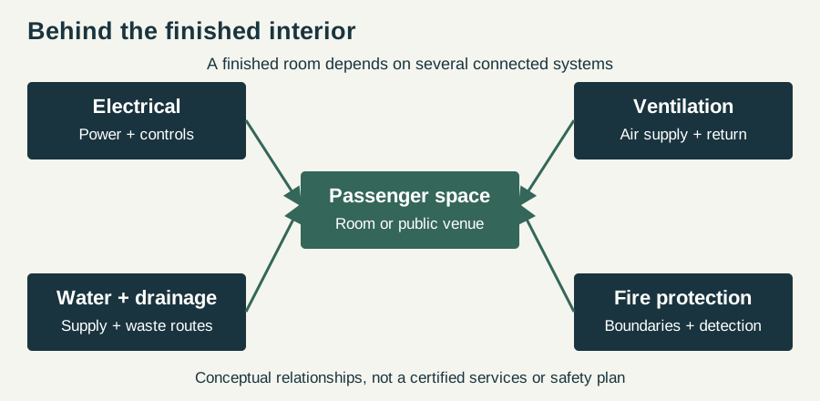
Cruise accommodation depends on networks that extend far beyond an individual cabin. Electrical cables deliver power, ventilation distributes conditioned air, pipes carry water, and drainage removes waste. Each service has its own routing and connection needs. A prefabricated room can be substantially complete while the networks that allow it to function are still being assembled around it. Physical installation and operational readiness are therefore different measures of progress.
The diagram below groups these services by function. It is not a piping plan. Its purpose is to show why a connection between two blocks is both structural and functional: cables, ducts and pipes cross the same construction boundary. A completed wall or ceiling can conceal unfinished work, which is one reason photographs of interiors cannot establish whether a whole zone has been commissioned.
Fire protection adds another layer. IMO’s fire-safety framework covers protection, detection and extinction. A route that passes through a protected boundary must preserve the purpose of that boundary; the engineering task is not merely to find a convenient hole. Alarms and suppression equipment must also be integrated with their controls and supplies. The result is a ship whose apparent rooms are connected by a much more complicated set of technical relationships than a passenger normally sees.
Sources: [7] IMO: fire protection aboard ships ↗
Commissioning: prove each system, then prove the ship
Commissioning turns installed equipment into a working installation. At a basic level, this means checking that components are connected, configured and able to perform their intended functions. At the next level, it means checking interactions. A pump may run successfully by itself but still require the correct valves, electrical supply, sensors and control logic to serve the completed system. Progress is therefore better described by completed tests and resolved findings than by counting installed pieces of equipment.
Propulsion is a clear example. The engine or motor, distribution equipment, cooling, controls and propulsor must work together. Bureau Veritas’s machinery rules distinguish dock tests and sea-trial requirements, including relevant checks for electric propulsion and manoeuvring. The particular programme depends on the vessel and applicable requirements. There is no single universal checklist that a short article can substitute for the project’s approved test programme.
Sea trials move the investigation into an operating environment. They are not simply an early pleasure voyage for an empty ship. Equally, a trial photograph cannot tell the reader which tests were performed or what the results were. The responsible interpretation is narrower: the ship was at sea at a particular stage. Claims about achieved speed, manoeuvring performance or acceptance need the corresponding records or statements from the parties involved.
Sources: [9] Bureau Veritas: machinery testing requirements ↗
Why a construction schedule is a network rather than a countdown
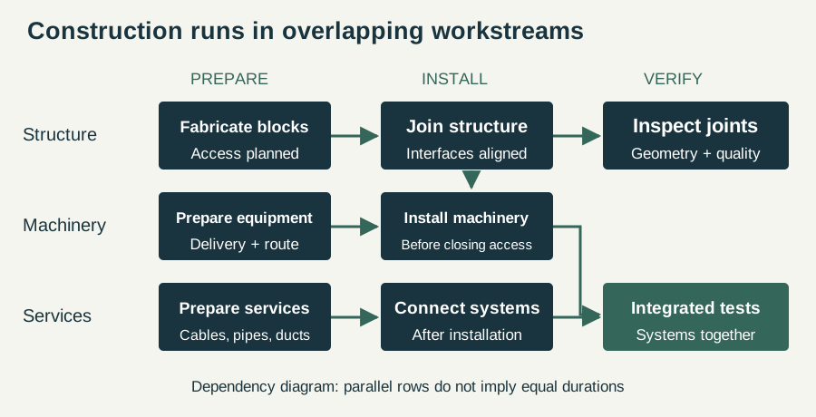
A simple timeline suggests that one task ends and another begins. Actual assembly allows many activities to overlap, but only where their dependencies permit it. Suppose a fictional project has a machinery installation that requires an open deck, a cable connection that requires that machinery to be fixed in place, and an enclosure that would block the installation route. Those tasks cannot be rearranged arbitrarily. Other work elsewhere on the vessel may proceed at the same time.
This creates a distinction between elapsed time and accumulated work. Ten teams working for one day produce ten team-days of effort, but only one day passes on the calendar. A time-lapse compresses that already parallel process even further. It should not be used to infer the labour required from the few minutes visible onscreen.
A delayed task matters most when it holds up activities with no remaining scheduling flexibility. Adding workers to an unrelated area will not necessarily solve that dependency. This is the practical reason why shipbuilders pay attention to material availability, access and the order of installation alongside dock capacity. The schedule diagram illustrates these relationships without assigning invented durations to a real yard. The central question is not simply how fast a block can be lifted, but what must be ready before and after that lift.
How to watch the time-lapse below
First follow the growth of the hull: which large sections appear as complete lifts? Next watch the upper decks and openings. Finally compare the apparent exterior completeness with the remaining activity around the vessel. Time-lapse compresses the pauses and overlaps that make a real construction schedule complicated. It is excellent evidence of visible assembly but poor evidence of how many labour hours a task took or whether unseen systems were complete. Use the film as a companion to the construction sequence, not as a stopwatch or a universal template for every yard.
Watch the engineering in action
Sources & further reading
An editorial explainer based on the technical, research and industry references below.
- Meyer Werft: modular construction ↗
- Meyer Werft: production ↗
- Oceania Cruises: Sonata float-out announcement ↗
- Meyer Werft: digital design and production ↗
- DNV: ship classification ↗
- IMO: ship design, subdivision and stability ↗
- IMO: fire protection aboard ships ↗
- Wärtsilä: model testing ↗
- Bureau Veritas: machinery testing requirements ↗